Piezoelectric Sensors
Here you will find all of the information related to the Piezoelectric Sensors used in the Bambu Lab P1 and X1 series printer. These bed sensors can be reused for auto bed levelling with a simple XIAO RP2040. For now, reuse of the Piezoelectric Sensors is destructive, and requires soldering / crimping permanent connections to the original cable. You can also apply this entire page to using the Piezoelectric Sensors in ANY printer you want!
Just note, this WILL be annoying for P1K builders. Theres a lot of crimping, and your setup is likely to look like a rats nest of DuPont cables, or an improvised explosive device, whatever is funnier to you. I strongly recommend grabbing a Biqu Microprobe or Beacon3D Eddy Scanner opposed to reusing the original sensors, but if you wish to reuse these still then you can. It won’t be fun!
The code used on the XIAO RP2040 WAS GENERATED BY AI. AI generated code can have issues, I am really sorry about using AI for this, but I am not the smartest person on the planet 😔 USE AT YOUR OWN RISK.
Bill of Materials
You are not required to use these specific parts, you may need to find alternatives due to tarrifs. You may substitute a XIAO RP2040 with a Pi Pico. You may substitute EC360 Glue for any other non conductive glue. You are expected to already have JST XH connectors from the previous BOM, they are not included in this BOM. Prices do not include shipping!
| Part | Quantity | Option | Price (USD) |
| SEEED Studio Xiao RP2040 | 1 | XIAO RP2040 | $3.90 |
| DuPont Jumper Pins | 1 | “10CM KIT” | $3.00 |
| DuPont Crimp and Connector Set | 1 | “Kit” | $4.50 |
| Breadboard | 1 | “Tiny Premium Breadboard” | $4.00 |
| EC360 Glue | 1 | “30G” | $10 |
If you are following this guide to apply these sensors to other printers, then grab all of these:
| Part | Quantity | Price (USD) |
| Heatbed Piezo Interface Board | 2 | $12.00 |
| Heatbed Sensor Interface Board | 1 | $3.00 |
| Heatbed Sensor Unit | 3 | $15.00 |
| PicoBlade Connectors | 1 | $6.00 |
Piezo Carrier Board Pinout
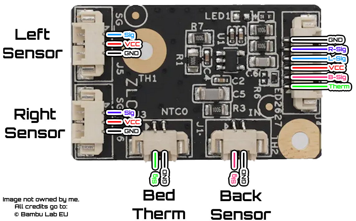
So how the hell does this work?
We will be using a XIAO RP2040 board with firmware that supplies the Piezo Board with 3.3V, and reads R-Sig, L-Sig and B-Sig on analog outputs A0, A1 and A2. The firmware reads all 3 outputs of the Piezoelectric Sensors, and once 1 (or multiple, can be configured) triggers have been detected, the RP2040 outputs high to D6, this D6 pin should be connected to any available endstops SIGNAL port, make sure to also connect ground to the XIAO RP2040. The firmware provided was not written by me, unfortunately was written by AI as stated in the warning so please use at your own risk, I am not responsible for damages caused to your printer. Again, I strongly recommend grabbing a Biqu Microprobe or Beacon3D Eddy Scanner instead of doing this annoying bullshit.
Flashing the RP2040
Flashing the XIAO RP2040 is ridiculously easy, download Arduino IDE. Navigate to File -> Preferences, in the “Additional boards manager URLS” window, paste the following GitHub Link there. Once this is added, navigate to the boards manager tab, type RP2040 and download “Raspberry Pi Pico/RP2040/RP2350 by Earle F. Philhower”, after that simply plug your XIAO RP2040 into the PC and it should be detected. Copy paste the code on the GitHub Repo into the window, then click the upload arrow in the top left of IDE. It should flash successfully and you are likely to get a serial output that is just spamming “Piezo Triggered”.
Crimping & Despair
You will crimp all cables with DuPont style connectors, if you followed the guide prior to this page then this cable would already be crimped to a JST XH or plugged into my breakout board. You may want to use the rest of the breadboard here to take the thermistor pin from Dupont -> JST back to the mainboard of choice. Using the pinout images above, trace each pin from the Piezo Board back to the rear of the printer, and connect the signal pins in any order to pins A0, A1 and A2. Connect D6 to any endstop port and make sure GND is shared all around. The breadboard makes this process super easy as you can tie GND from the thermistor etc together with ease. After this, you are ready to plug the RP2040 in. Connect a Type C cable to your RPI or a dedicated 5V source. (This is just for power) And boot up your printer.
Klipper Configuration
If you have a probe defined already, # it out and add the following:
[probe]
pin: # Add your endstop pin here
x_offset: 0
y_offset: 0
z_offset: 0
speed: 5
lift_speed: 5
sample_retract_dist: 5
samples: 1
Now, time to test your handy work. In the mainsail console, type QUERY_PROBE. If it says the probe is triggered, then make sure to remove ^ from the pin used, or do the opposite and add it. It should state OPEN in a normal state. Befre we test the Piezos, please lower your Z axis way down manually by just pulling on the belts underneath the printer so you don’t obliterate your nozzle or toolhead. Time for the scary part, testing. While tapping on the bed repeatedly, run the command QUERY_PROBE over and over again, if you do not get a trigger command then your wiring could be incorrect or the parmeters of the code need to be adjusted.
What to tune in order:
-
Reduce false triggers during Z motion by adjusting
static const float SLOPE_THRESHOLD_V = 0.030f;. Increasing this value will filter out false triggers caused by vibrations of the motion system. -
Require a bigger deviation from the baseline threshold. Adjusting the value of
static const float DIFF_THRESHOLD_V = 0.180f;upwards will make the piezos need a bigger deviation to trigger. -
The risky one is
static const float ABS_HIGH_THRESHOLD_V = 2.80f;. If you aren’t getting any triggers and you are certain the wiring is correct, slowly lower this value.
If you have any issues beyond this point and cannot get a trigger by manually tapping the bed, PLEASE contact me on my Discord Server! before you damage your printer.
If you are getting triggers, then you can send the command G28 Z, hold your cursor over the emergency stop button and tap the bed with your hand, it should trigger just from the lightest tap ever, if it requires a really hard knock then emergency stop, please adjust the values above until it triggers with ease. You can then try allowing the printer to home itself with G28 Z again, it should trigger without bending the toolhead or causing any flexing. Please also run a PROBE_ACCURACY command, you should expect a range between 0.01 and 0.005, this is expected. If it is higher, again please try to adjust the values above. Once I have a fully working P1K on Piezos, these values will be pre-tuned ready for you.
Ta-da, you homed with the original sensors, now it’s time to set a Z_OFFSET. But Chaz, I thought it would be 0 since the nozzle touches the bed? Nah, doesn’t work like that. Run PROBE_CALIBRATE, grab a piece of paper and slowly adjust the bed until you get light friction on the bed, save and restart. You will now need to also adjust your bed mesh min and max values, I highly recommend this video by PrintsLeo3D, it has helped me countless times for getting the correct min_max values.
Run BED_MESH_CALIBRATE and carefully watch the whole process, the sensitivity should be equal from front to back with no zones pressing harder than the other.
Done!