Disassembly
Introduction
During disassembly, we will be removing the MC board, chamber cooling fan and a lot of toolhead parts. You will need a 2.0 and 1.5mm Hex Key and preferably somewhere to store each screw. There are plenty of printed designs available on Printables and similar.
Time Required: 30-45 minutes
Begin
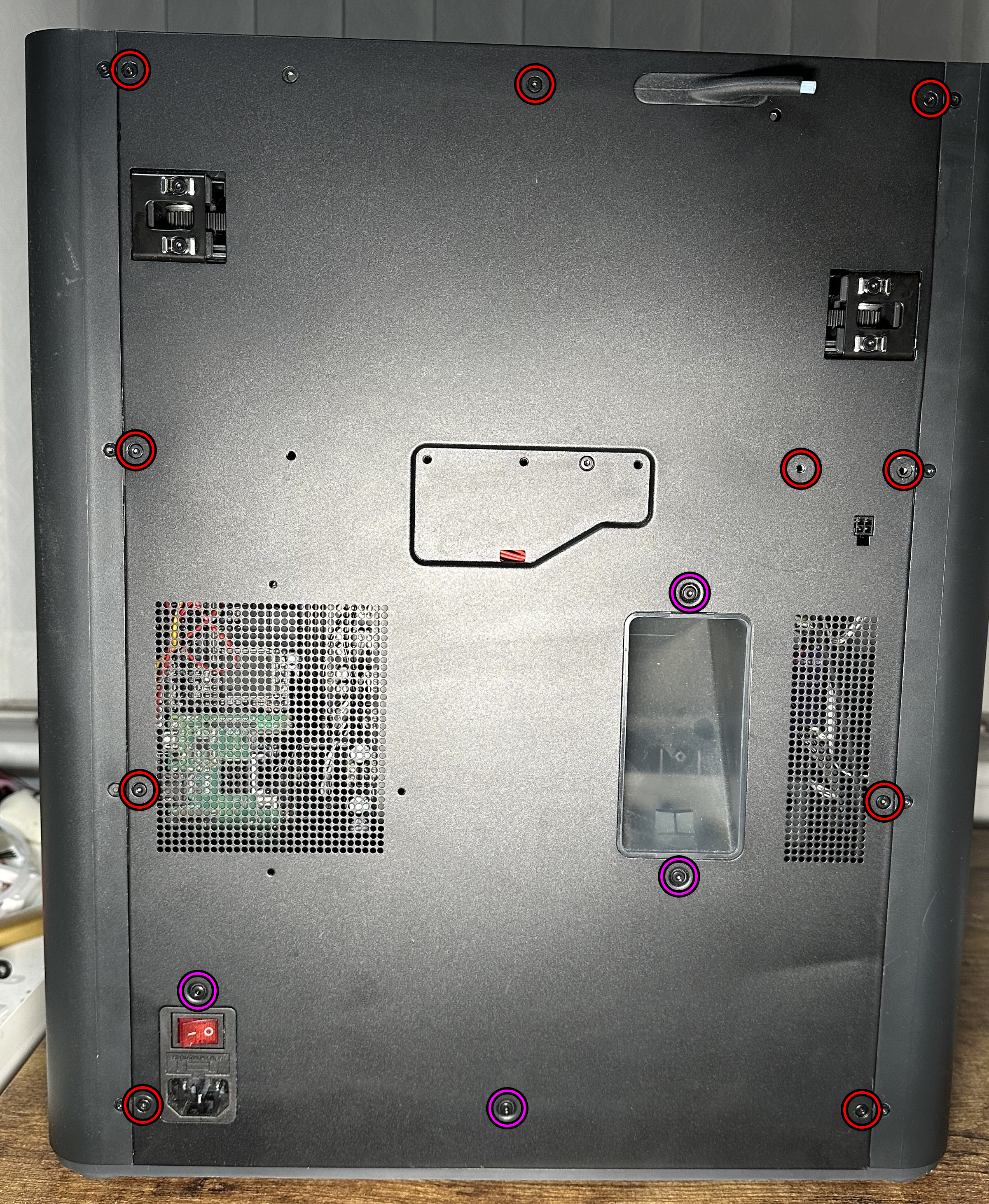
We will start at the rear panel, remove your filament and disconnect your power cable if you havent already. To start, remove the 4 self tapping screws highlighted in Magenta. Once these screws are removed, continue to remove the rest of the 9 normal threaded screws highlighted in Red, including the two used for the spool holder if you have it installed.
You can now remove the panel and gain access to the rear electronics.
Remove the Purge Chute
To remove the Purge Chute, remove the two screws up top as shown, pull down then outwards.

Remove the Chamber Circulation Fan
To remove the chamber fan, first unscrew the fan from the plastic holder, this will give you access to the 4 self tapping screws, carefully remove these without dropping them, it will help to place something underneath to catch them as they will be a pain to remove. Remove the whole assembly, this is where the new mainboard is going to live. Keep hold of those self tapping screws, we will be reusing those later.
Remove the MC Board
Start by unplugging everything you can see, please use a pair of tweezers and avoid pulling on the wires, the crimps can be quite weak. Once all visible cables have been unplugged, remove the 4 screws which hold the MC board in place and pull it out, we wont be needing that anymore.
Toolhead Disassembly
We will need to remove all of the plastic covers so that we can neatly route the wires. First pull off your fan cover and disconnect the fan cable.
If you are reusing your hotend, remove the hotend by unscrewing the two screws which fix it in place and disconnect the rest of the cables.
To remove the side covers they are both attached with 4 self tapping screws each. To make it easier to remove the middle cover, you should loosen the cutter arm until it hangs below and then remove all 8 screws. Remove the rear cover first then the middle cover by bending it outwards slightly.
You will now have access to the rear toolhead board. This toolhead board cannot be reused, so it should be removed. Carefully disconnect all of the visible cables on the front of the board, the toolhead cable connects to the rear of the board. Remove the 3 screws that are fixing the board in place, once the toolhead board is loose disconnect the rear cable. This cable will also need to be removed from the cable chain.
First pull the chain off the toolhead making sure the cable is loose from it first, you can do this by rotating it until there is a slot available to pull the cable out. Once it has been lifted up, move to the rear of the printer and remove the screw that holds the cable chain in place. Unlock the cable chain cover by pushing, it should bend out slightly giving you the access you need to remove the cable. Start pulling the cable out of the chain and push it down the hole. If you want to remove your cable chain assembly, now is the time to do it. It should just pull right out as it is all just press fit. Avoid pulling just the actual chain off.
Finalising
If any other cables or such are visible, now is the time to pull them all through. You can leave your original AP board and original screen in place, they won’t be reused but it doesn’t harm to leave them be at all, makes it easy if you ever want to go back. Ready to start assembling?