Assembly of your P1K
Introduction
You may find it handy to use Wiring - Mainboard as it goes into further detail about wiring. During the reassembly you may find yourself getting stuck or having difficulty wiring up, this is normal and I have included tips everywhere I can to make the whole process a bit smoother. We will start at the toolhead.
This page applies to:
Mainboard: Manta M5P
Time Required: 45-60 minutes
Wiring Diagram
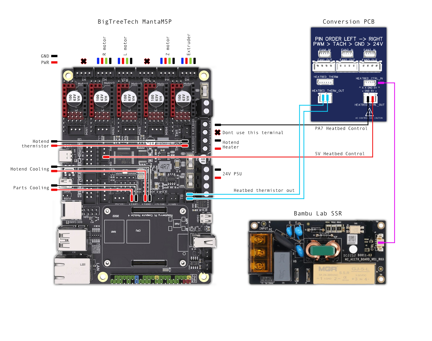
This image currently doesn’t cover using the PWM & Tach fans, this can be done via the Raspberry Pi CM4 / BTT CB2’s GPIO pins. If you need assistance with this let me know on the Discord.
The thermistor polarity for the heated bed does matter in this case because of the Piezo PCB’s underneath the bed, if you get a wild reading of -1000c or something, flip the cables around and it should clear up.
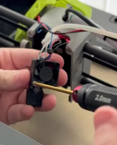
Assembly Start
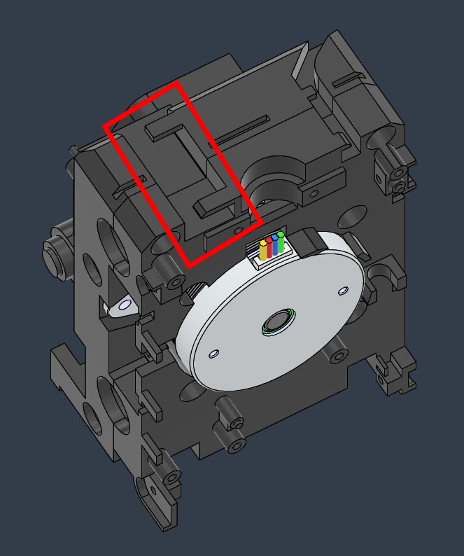
Begin with installing your newly wired hotend along with the Delta 2510 fan, all of the cables will be routed where the ribbon cable lived. Secure your hotend with two screws. Once the hotend & 2510 fan is installed, you can also plug your extruder motor into it’s extension cable.
I recommend that you route your cables now as it’ll be hard to route once the middle cover is installed, I also recommend loosely routing the 5015 fan now since the cable wont be able to be routed after the middle cover is installed (Unless you are using a detachable 5015 fan with a short JST cable).
Once all these cables are routed properly, secure the filament cutter and proceed to installing the middle plastic cover. Once it snaps into place, secure it using the 4 self-tapping screws. Now that your middle cover is installed you can re-secure the 5015 fan in your choice of fan cover. You can also now magnetically attach your Fan Cover and attach the rear cover. Please make sure your cables are routed up and through the cable chain before reattaching the rear cover if you are using that. Don’t forget to secure the 4 self-tapping screws which the rear cover uses, these only need to be snug!
If you are struggling here, I would definitely give the Bambu Lab wiki a look as it covers disassembly quite well.
I don’t use the cable chain because it is too small to accomodate the amount of wires in a wiring loom, but if you route each wire individually through the chain you might be able to get away with it.
Cable Routing
Start to route the cables from the toolhead through the hole which the P1 originally used. If you have the cable chain installed, there is a screw on the rear of the machine which needs to be removed so that you can remove the plastic cover and gain more access. If working with a P1P, just start pushing each cable through the cable retainers and down into the rear electronics bay. The P1 does include some cable management clips, but they weren’t designed for this many cables, so use them sparingly.
Adapter PCB (If you are using one)
This part is really easy, using 4 of the screws that we stole from the MC board, attach the MC board being careful not to strip the plastic threads, these need to be snug and nothing more. Plug the cables in according to the wiring diagram and leave the heatbed control cables loose for wiring.
Electronics Box
After you have pulled your cables through, it’s now time to mount the electronics box. We must do this before installing the motherboard because it can be very annoying to route cables in this tight space. But before we mount the electronics box, install cable ties into the holes so that you can neatly organise the power cables so that they do not rub on the Z axis. Once your cable ties are installed, using 3 of the screws stolen from the Chamber Circulation Fan you can attach the electronics box into the rear of the printer where the Chamber Circulation Fan used to live.
Before we mount the Manta M5P into the box, I highly recommend pre-routing some cables, primarily the hotend’s thermistor, fans and microprobe cables through the hole at the top. Start by first attaching your heater and 24V input cables, you should route these through the holes on the side and screw them into the Manta according to the wiring diagram (With it loose, do not mount it yet). Once these cables on the side have been screwed in, we can now properly screw the Manta in.
Using 3 M3X6 (Or M3X8) screws, securely attach the Manta into place making sure no cables have been squashed or run underneath. Once attached, begin to plug in your hotend thermistor cable, fans, microprobe, stepper motors etc according to the wiring diagram. This part is really easy, just plug in and good to go, once you have attached all of these cables, it’s time to begin some cable management.
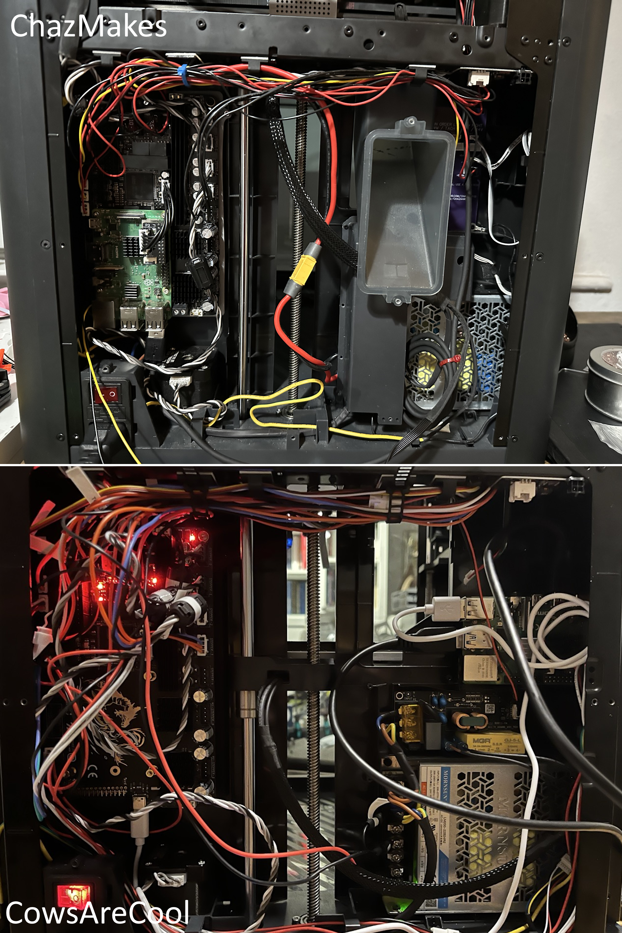
Cable Management
So, it’s all wired up, I highly recommend that you begin testing the printer at this stage so you can diagnose any problems. You can go to the commissioning tab to get started testing. Just make sure no cables are getting kinked or squashed by the Z axis.
Everything working as it should? Now is the time to start managing these cables. Before you start using zip ties, ensure your gantry can move freely with some light slack into wiring loom. Once thats good, use 3-4 zip ties on your wiring loom and manually move the axis around, be careful here you don’t want to fry your TMC drivers. If all is good here, move back down to the rear, I highly recommend using the stickyback zip tie cable management things here, pre-load them with your cable ties and start clumping all those wires together, it’s a good idea to leave some slack on these too. Ensure that no cables are getting pinched or moved by your Z axis, you can tilt the printer and move the belts yourself underneath the printer to check. On the side of your electronics box, neatly route the XT60 downwards and make sure the Z axis also doesn’t rub against it