Introduction
This section covers preparing the toolhead, splicing and soldering wires etc.
What you will need:
- Your 3D Printed fan cover.
- A Bambu Lab hotend, with the X1C Heaters & Thermistors.
- 22AWG & 24/26AWG wire.
- A 5015 fan (The stock Bambu Lab 5015 can work here, but it will be destructive).
- Delta 2510 fan (The stock Bambu Lab 2510 can work here, but it will be destructive)
- BIQU Microprobe
Time required: 1 to 2 hours.
Bambu Lab Hotend Wiring
To begin, you will need to splice the thermistor cable, as it uses a JST GH connector. It is possible to crimp JST PH to this connector but it is very difficult and I recommend against it.
Cut off the JST GH connector as close as you can to give you more wire to splice, then using a wire stripper or flush cutter, strip the cable carefully. It’s easy to fail here, this thermistor is very difficult to strip. To solder, tin the spliced thermistor wires, then using some 24 or 26AWG wire solder on ~60cm extension wires if you want to be forgiving with cable length and dont mind some cable management afterwards. Please use heat shrink once you have soldered the extension wires, once that is done, crimp on a JST XH 2.54 connector for use in the mainboard.
The heater is already pre-crimped with a JST XH 2.54 connector, so its as simple as wiring up a extension cable with a female XH connector on the heater side and crimping on some ferrules on the mainboard side. I recommend using 22 AWG here as the heater is drawing 24V 48W of power. I linked to some of these “female XH connectors” in the BOM which work well for me.
New Fan Wiring
Delta 2510 Fan Wiring
The Delta ASB02505SHA-AY6B fan runs on 5V only, so please ensure that you are supplying 5V to the fan to avoid causing damage. Double check your jumper positions on the Manta M5P.
This one is really easy, there are 3 wires on the Delta ASB02505SHA-AY6B.
- 5V VIN
- GND
- Tachometer
This fan comes pre-stripped and tinned for your convenience from all available outlets, so just solder on extension cables to the fan. 5V will be the light red/pink wire, GND is black and Tachometer is Blue if you want to use that, but it is not configured to do so.
Optional: You can crimp on a 3 pin JST XH connector to this fan to make it easily swappable, but you will need to also buy 3 pin JST female headers.
New 5015 Wiring
There is none! The fans linked in the BOM come pre-crimped with a 2-Pin JST XH 2.54 connector, with long cables. Just check that the pins are the correct way around according to your motherboard, or replace the 2P connector for a 3P one if your board uses that.
Stock Fan Wiring
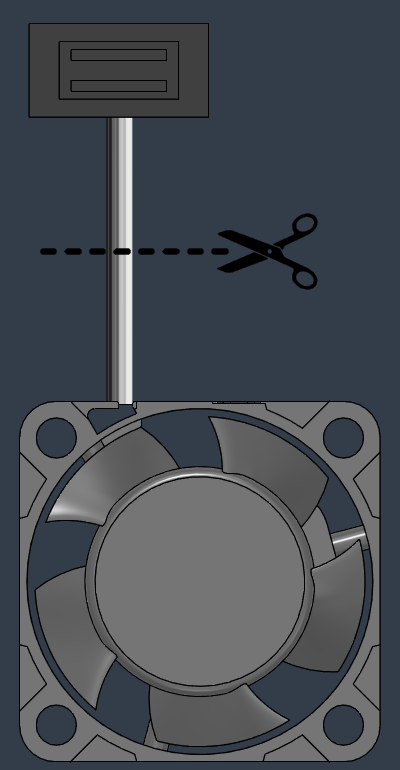
Stock Bambu 2510 Fan Wiring (DESTRUCTIVE)
This step is destructive and will require re-soldering if you plan to swap back to stock. If you are comfortable with this, proceed forward. The Stock Bambu Lab Fan runs on 5V, please ensure that you are supplying 5V to the fan to avoid causing damage. Double check your jumper positions on the Manta M5P.
It has come to my attention that Bambu has changed the pinout of their fans, please double check the pinout on your fan. This can be done by peeling back the sticker, if there is epoxy or similar covering the solder joints, contact me on Discord.
There are 4 wires on the Bambu Lab 2510 fan, all fans on the Bambu share the same colour scheme. You will need to cut off the mezzanine connector which the 2510 fan uses, then strip each wire.
- 5V VIN (Black)
- GND (Dark Grey)
- PWM (White)
- Tachometer (Light Grey)
Repeat the same steps as the Delta 2510 fan, solder on your extension cables. On the M5P you will need to wire the fan up to 5V and GND, then control it via PWM using one of the Pi’s GPIO ports. You can also monitor the tachometer output via the Pi’s GPIO ports.
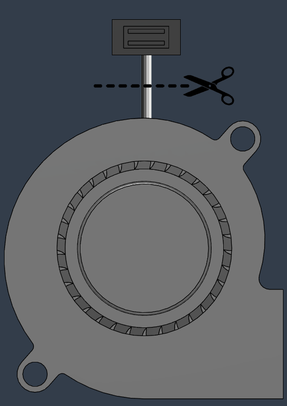
Stock Bambu 5015 Fan Wiring (DESTRUCTIVE)
This step is destructive and will require re-soldering if you plan to swap back to stock. If you are comfortable with this, proceed forward.
There are 4 wires on the Bambu Lab 5015 fan. You will need to cut off the mezzanine connector which the 5015 fan uses, then strip each wire.
- 5V VIN (Black)
- GND (Dark Grey)
- PWM (White)
- Tachometer (Light Grey)
Repeat the same steps as the stock 2510 fan, solder on your extension cables. On the M5P you will need to wire the fan up to 24V and GND, then control it via PWM using one of the Pi’s GPIO ports. You can also monitor the tachometer output via the Pi’s GPIO ports.
Extruder Motor Wiring
The extruder motor is just a standard Nema 14 with a helical gear. There is nothing special about this motor. All you need to do is create an extension cable that copies the motors pinout with a Female JST XH 4P connector, with a Male connector on the opposite side. I linked to these on the BOM. Take 4 24AWG wires, each with different colours, strip them and solder them to the Female XH connectors, then crimp on a male JST XH connector.